 UDOO Neo Documentation
Device Tree Editor
Introduction
The device tree is a data structure used for describing hardware. The device tree is compiled by the device tree compiler (dtc), which produces binary .dtb files (also known as flattened device trees, or fdt).
The data structure is a tree of named nodes and properties and it can hold any kind of data. Nodes contain properties and child nodes, while properties are name–value pairs. More informations are available on here and here.
UDOObuntu provides out-of-the-box device tree blobs, available in /boot/dts/, for all possible combinations of board type, screen type and M4 core status. For example, UDOO Neo Basic can use the following files:
imx6sx-udoo-neo-basic-hdmi-m4.dtb
imx6sx-udoo-neo-basic-hdmi.dtb
imx6sx-udoo-neo-basic-lvds7-m4.dtb
imx6sx-udoo-neo-basic-lvds7.dtb
imx6sx-udoo-neo-basic-lvds15-m4.dtb
imx6sx-udoo-neo-basic-lvds15.dtb
imx6sx-udoo-neo-basic-m4.dtb
imx6sx-udoo-neo-basic.dtb
Theboot loader loads the correct dtb file, depending on the board.
Custom device trees
While the board can be used with the default device tree, which exports most of the external pins as GPIO, it is also possible to export more features on the external pinout. See the section Pinmuxing to discover all the exportable configurations.
On UDOO NEO the external pins can be connected to the Cortex-A9 core (the one that runs the Operative System) or to the Cortex-M4 core (the one that implements the Arduino microcontroller).
UDOO Neo provides a graphical tool to change this configuration called Device Tree editor. Open if from the START menu -> Preferences -> Device Tree editor.
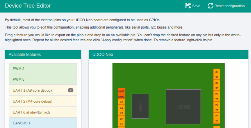
To remove the feature you need to right-click on a dark orange pin in the right panel.
After the functions are selected you can save by clicking on the top Save button, and then reboot the board.

I2C-2: SNAP-IN Bricks connector
By default the snap-in connector is assigned to the A9 and it’s possible to control it by Linux driver. The I2C signal are also available on SDA - SCL pins and on pins 36/37.
If you need to use this on the M4 Arduino core, you need to remove it from the A9 core, right-clicking on the corresponding pins and removing it.
After a reboot it will be possible to connect an external I2C device to the SDA SCL pins and control it from the Arduino M4 core.
I2C-4 Motion Sensors bus
By default the internal 9-axis motions sensors are assigned to the A9 and it is possible to control them by Linux driver. The I2C signals are also available on pins 34/35.
If you need to use them by the M4 Arduino core you need to remove it from the A9 core, right-clicking on Snap-in connector and remove it.
After a reboot it will be possible to connect an external I2C device to I2C-4 pins and controll it from the Arduino M4 core.
The IOMUX
The i.MX processor has several pins, most of which have multiple signal options. These signal-to-pin and pin-to-signal options are selected by the input-output multiplexer called IOMUX. The IOMUX is also used to configure other pin characteristics, such as voltage level, drive strength and hysteresis.
i.MX 6SoloX implements many features and can export their signals on external pad. Each pad has no fixed signal but can be changed at boot depending on the needs of the manufacturer.

Every feature has one or more signals to implements its function and not all the feature can be exported at the same time on chip pads. Some of these pads are connected to external pins available to the user for connecting extra hardware or connections.